At JLI vision, we often work with global companies that have production sites in different parts of the world and want to implement the same type of vision system on several production lines.
The aim is, of course, to achieve consistent quality, but this exercise is not as easy as you might think. In this article, we dive into how we ensure that multiple vision systems perform the same under different conditions.
The fact is, if you buy five identical vision systems and place them in five different factories, you can’t be sure that they will deliver identical results in quality control.
Even if the hardware and software are the same, slight variations in setup, environmental conditions, and component behavior can cause inconsistencies. However, there are ways to standardize your vision systems to ensure consistent quality control across production lines.
Why identical vision systems don’t always behave identically
It’s easy to assume that two identical machine vision systems will perform the same. In reality, small deviations across multiple systems can lead to noticeable differences in results. A few key factors contribute to this:
Component variations. Even cameras and optics from the same manufacturer can have minor differences due to production tolerances.
Positioning inconsistencies. Placing a vision system in exactly the same way on different production lines is challenging, and small misalignments can impact performance.
Ageing of components. Over time, LEDs dim, optics shift, and sensors degrade, leading to drift in image quality and accuracy.
To overcome these challenges, proper calibration and system alignment are essential.
How to standardize vision system performance
1. Calibration with known references
One of the most effective ways to ensure consistency is by calibrating all systems against a known reference.
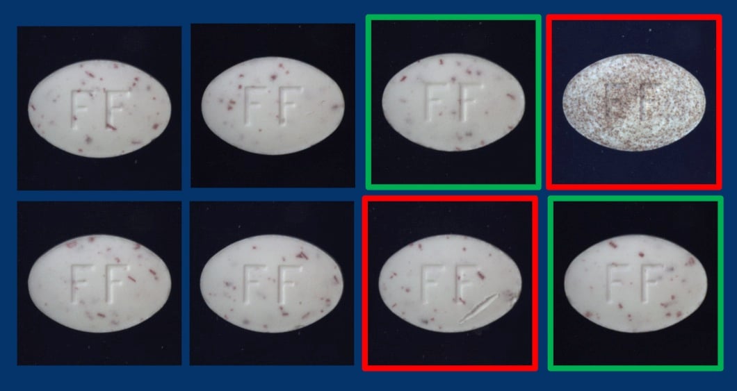
For example, if you’re measuring the diameter of small pellets, you can use a calibration object with a certified dimension—say, exactly 1 mm ± 2 microns. By running this reference object through all systems, you can adjust them to produce identical measurements.
Similarly, if your cameras perceive color differently, a color checker can help align them. You measure how each system interprets colors, then apply correction factors to normalize the results across all systems.
.jpg?width=1920&height=1729&name=Color%20Inspection(1).jpg)
2. Compensating for lighting differences
Light sources degrade over time, which can lead to variations in image brightness and contrast between systems.
By using a color checker, you can measure and adjust illumination to ensure consistency. Some systems allow dynamic light compensation, where power can be adjusted to maintain uniform brightness.
3. Ensuring uniform mechanical setup
Even with calibrated systems, mechanical placement plays a major role in achieving consistent performance. Differences in the distance between the camera and the object can impact measurements.
For small objects, a telecentric lens helps maintain the same magnification regardless of slight distance variations.
For larger setups, ensuring identical mounting is critical. We use 3D printed templates for this. Custom frames that we design to control the exact positioning of cameras and lighting.
Additionally, CAD models of the mechanical setup can provide machine builders with precise placement guides, ensuring uniform integration across multiple production lines.
Proper calibration and setup are needed
Two vision systems may look identical, but without proper calibration and setup, they won’t necessarily perform identically. By implementing structured calibration, compensating for lighting changes, and standardizing mechanical setup, you can ensure consistent quality control across multiple production lines.